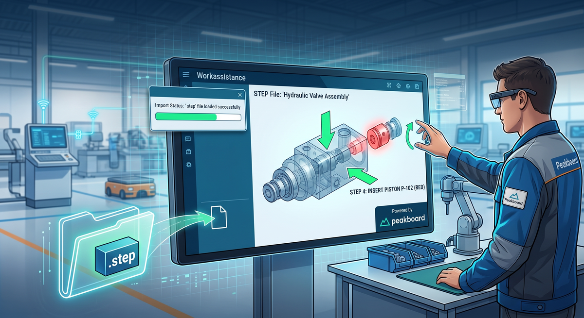
Every manufacturing company has the same treasure lying around unused: a CAD system full of 3D models that describe every single part in the plant down to the last chamfer. And every manufacturing company has the same problem at the assembly station: the worker gets a printed sheet with a grainy screenshot of that model, taken from whatever angle the technical writer happened to pick two years ago.
With the Step control introduced in Peakboard 4.4, that detour disappears. We drop the actual STEP file into a Peakboard application, and the model appears on the shop floor screen, rotatable, zoomable, and, most importantly, addressable from a script. In this article we build a complete worker assistance system around it: a five step assembly instruction where each work step shows exactly the parts that are already mounted and highlights the one that has to go on next.
Here is what we cover:
- What the Step control actually does
- Loading a model into the application
- The parts list, or how CAD geometry becomes data
- Driving the model from a work plan
- Interactive mode and performance mode
- The finished assembly assistant
What the Step Control Actually Does
STEP (ISO 10303) is the neutral exchange format that every serious CAD system can write, and it carries not just the geometry but also the assembly structure and the names of the parts inside it. Exactly the two things we need for a worker assistance system.
The control also reads glTF (.glb, .gltf), and where we have the choice that is the better option: a glTF file is already tessellated, so it opens faster and needs noticeably less memory than a STEP file, which has to be broken down into triangles every time it is loaded. We stay with STEP here because that is what comes out of the CAD system.
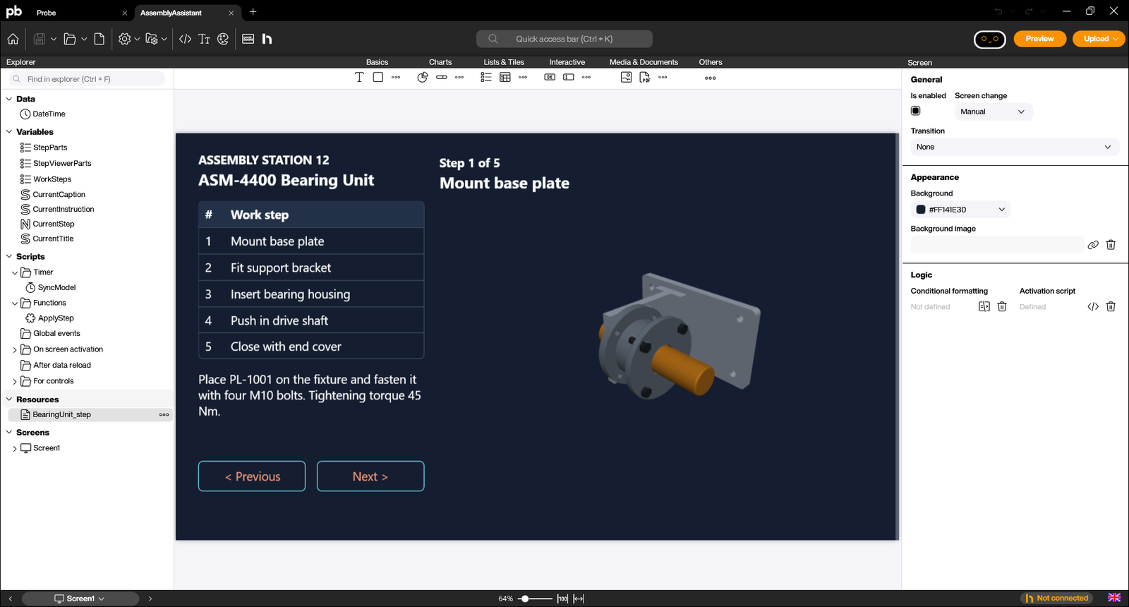
We find the control in the toolbar under “Others”.

Loading a Model into the Application
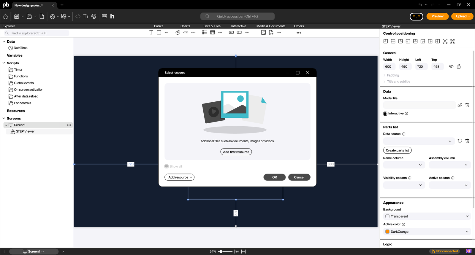
Dragging the control onto the canvas immediately asks us for the model file. STEP files are handled like any other Peakboard resource, and that choice matters more than it looks at first. A local resource is embedded in the project and travels with it to the Box, which is handy for a self-contained demo like the one we ship below, but it is rarely what we want in production: the moment engineering revises the part, the application still shows last quarter’s geometry.
In a real installation we point the resource at the place where the CAD data actually lives. The “Add resource” menu offers the full set: a network share read with a domain user, a plain web URL, Dropbox, Google Drive, Office 365, and the Peakboard Hub. The model on the shop floor screen then stays in sync with engineering without anyone opening the Peakboard project again.
For this article we use a small bearing unit assembly: a base plate, a support bracket, a bearing housing, a drive shaft, an end cover, and four hex bolts. Nine parts, each one a named product inside the STEP file. The names matter more than we might expect, and we come back to that in a moment.
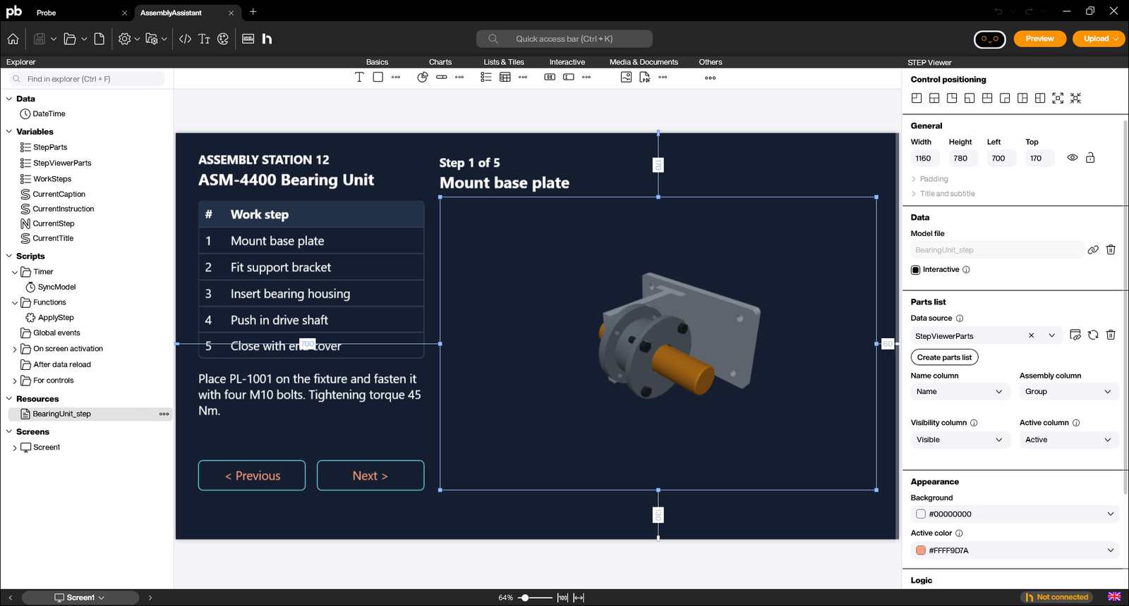
Once the resource is assigned, the model shows up directly in the Designer canvas, with the colours that were stored in the CAD data.
The Parts List, or How CAD Geometry Becomes Data
This is the part that turns a nice 3D viewer into an actual assistance system. The control does not just draw the model, it exposes every part of it as a row in a normal Peakboard list. One click on “Create parts list” and the Designer walks the assembly structure of the STEP file and generates a variable list with four columns.
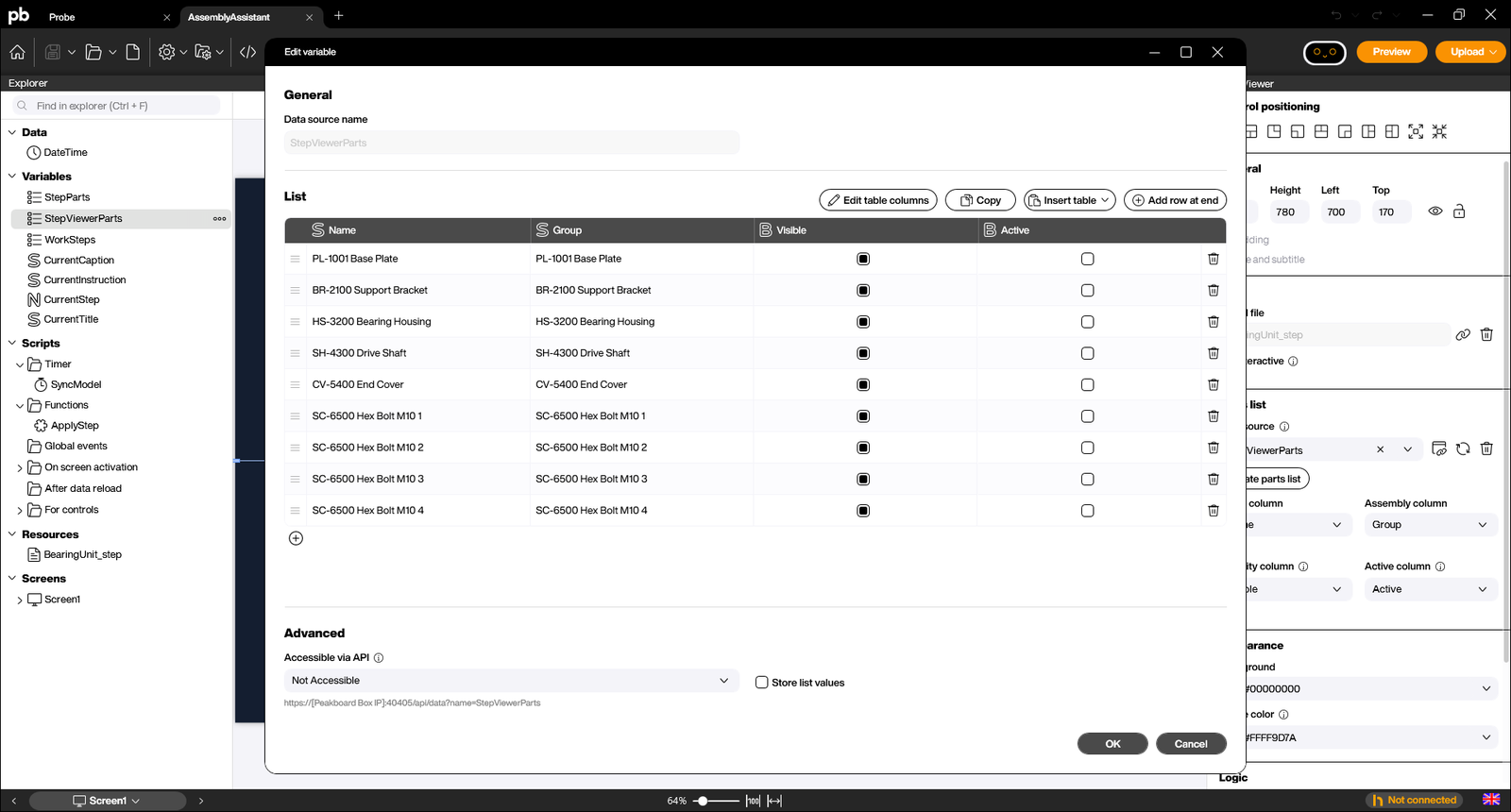
- Name is the product name from the STEP file. This is the key that connects the geometry to everything else.
- Assembly (stored in the Group column) is the node the part sits in. In a properly structured CAD assembly this lets us address a whole sub-assembly at once.
- Visible decides whether the part is drawn at all.
- Active highlights the part in the colour we configure as “Active color”.
The last two are the interesting ones, because they work in both directions of our data flow. When our script sets Visible to false, the part disappears from the scene. When it sets Active to true, the part is rendered in the highlight colour while everything else stays in its CAD colour.
There is one rule around Active that is easy to miss and that shapes the whole design: only one part can be active at a time. Marking a second part active silently clears the first, so the highlight is a spotlight, not a selection. Any time we want to emphasise a group of parts, visibility is the tool, not the highlight.
One detail is easy to trip over, so let us be explicit about it: the control writes the Name and Assembly columns itself whenever it loads the model. We should treat those two columns as read only and never abuse them to store our own information; it will be overwritten. Visible and Active are ours.
Driving the Model from a Work Plan
Now we can build the actual logic. The application holds three lists:
StepViewerPartsis the generated parts list, owned by the control.WorkStepsholds the five work steps with number, title, instruction text, and the one part that gets the spotlight. In a real installation this comes from the ERP routing rather than from a hard-coded list.StepPartsmaps each part name to the work step it belongs to. This is the piece that a real system would take from the bill of materials.
The split between those last two is exactly the single active part rule from above. StepParts may assign several parts to one step, and all of them become visible together; step five brings the end cover and its four bolts on screen at once. The Highlight column of WorkSteps then names the single part that carries the highlight, in that case the end cover.
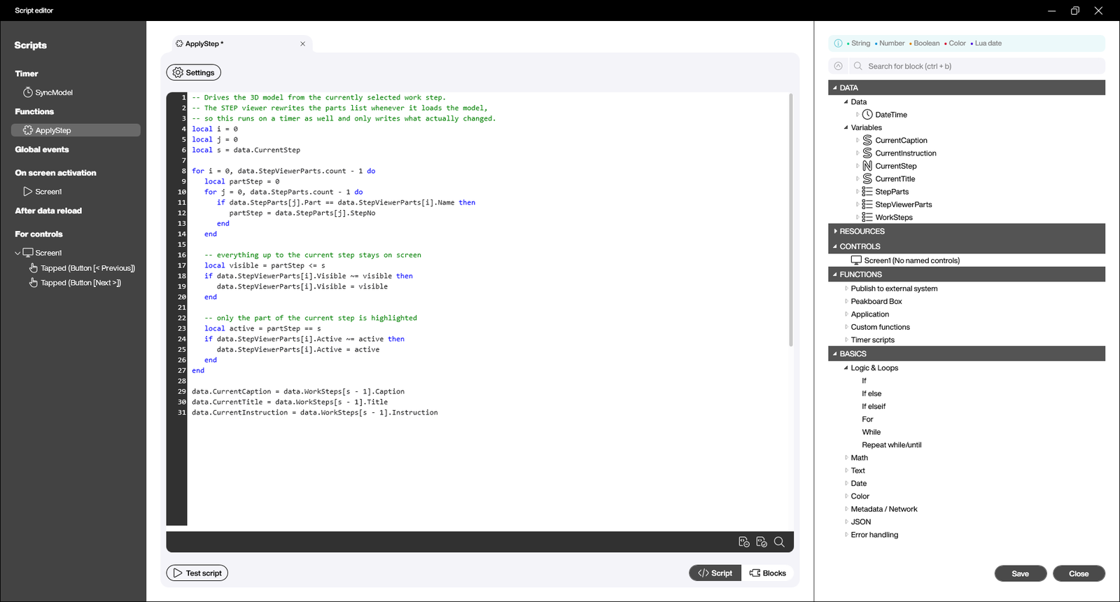
A single shared function, ApplyStep, does all the work. For every part in the model it looks up which step the part belongs to, then decides two things: parts of earlier steps stay visible so the worker sees what has already been built, and the leading part of the current step gets highlighted.
local i = 0
local j = 0
local s = data.CurrentStep
local highlight = data.WorkSteps[s - 1].Highlight

for i = 0, data.StepViewerParts.count - 1 do
   local partStep = 0
   for j = 0, data.StepParts.count - 1 do
      if data.StepParts[j].Part == data.StepViewerParts[i].Name then
         partStep = data.StepParts[j].StepNo
      end
   end

   -- everything up to the current step stays on screen
   local visible = partStep <= s
   if data.StepViewerParts[i].Visible ~= visible then
      data.StepViewerParts[i].Visible = visible
   end

   -- the control allows exactly one active part, so we highlight
   -- the single leading part of the step and nothing else
   local active = data.StepViewerParts[i].Name == highlight
   if data.StepViewerParts[i].Active ~= active then
      data.StepViewerParts[i].Active = active
   end
end
Two things in this snippet deserve a comment. The write is guarded by a comparison, so we only touch a property when the value really changes and the scene is not repainted for nothing. And the whole function is called from a one second timer rather than only from the buttons, because the control rebuilds its parts list when the model finishes loading and would otherwise reset our carefully set visibility flags right after start.
The two buttons are then almost embarrassingly simple:
if data.CurrentStep < data.WorkSteps.count then
   data.CurrentStep = data.CurrentStep + 1
   ApplyStep()
end
Interactive Mode and Performance Mode
Two checkboxes on the control are worth knowing about.
Interactive decides whether the worker may rotate and zoom the model with touch or mouse. For an assembly station this is exactly what we want, because being able to turn a part and look at the mounting point from the other side is the whole reason for showing 3D instead of a photo. Switched off, the control shows a static snapshot instead, which saves performance and suits a pure information display that just rotates through screens.
Performance mode, hidden in the Advanced section, is not the general quality switch the name suggests. The control renders in an embedded browser layer, and this mode keeps that layer permanently in the foreground. That is faster, but it comes at a price the tooltip states plainly: any control placed on top of the viewer is no longer visible. So it is the right choice for a screen where the model sits on its own, and the wrong one as soon as we want to overlay a badge, a button, or a callout on the 3D area.
The Active color completes the picture. The default is DarkOrange, and leaving it empty switches the highlight off altogether. We set it to the same accent colour the rest of the application uses, so the highlighted part reads as “this is the task now” rather than as a random colour change.
The Finished Assembly Assistant
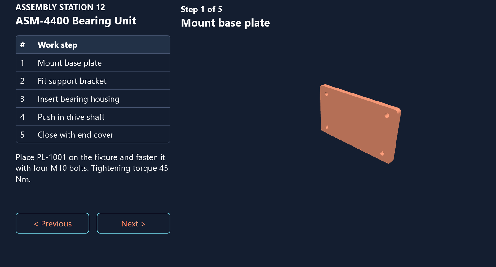
Here is the result. Step one, only the base plate exists, highlighted, with the instruction and the torque value next to it.
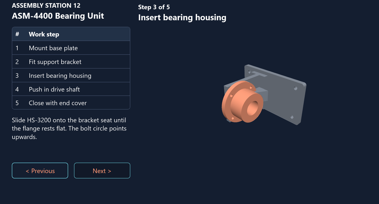
At step three the plate and the bracket are already in place and shown in their normal colour, while the bearing housing that has to go on now is highlighted.
And at step five the unit is complete: the end cover and its four bolts have appeared, with the cover carrying the highlight.
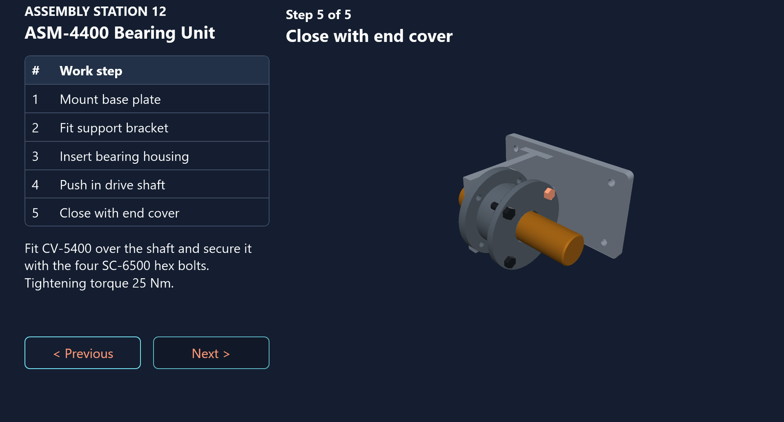
The worker can rotate the model at any point to look at a mounting point from a different angle, and the whole thing runs on a Peakboard Box without a CAD licence, a viewer installation, or a browser plugin.
What This Changes
The honest value here is not the 3D rendering; plenty of tools can draw a CAD model. The value is that the model has become a data source like any other. The parts of the geometry are rows in a list, the list is driven by a script, and the script is fed by the same ERP data that drives the rest of our shop floor applications. When engineering changes the part, we exchange one resource in the project instead of re-shooting a series of screenshots. When the routing changes, the assistance system follows automatically.
That is what makes it worth wiring up properly rather than just dropping a pretty model on a screen.
The complete application and the STEP file we used are available for download above. Open the pbmx file in Peakboard Designer 4.4 or later, hit Preview, and click through the steps.