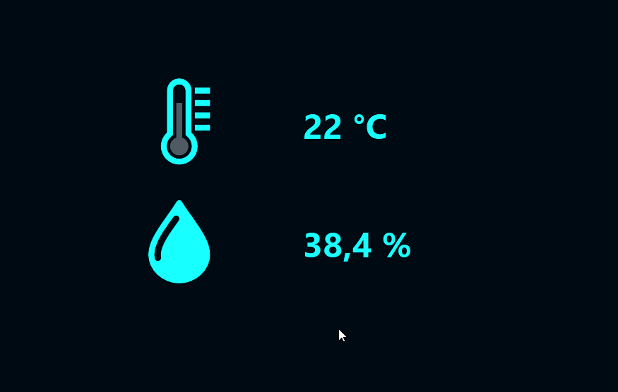
Modbus is a standardized protocol for addressing sensors. It was invented by Schneider Electric back in the late 70s, but is still widely used. In this article, you will learn how to use the Peakboard Modbus data source to address a sensor, get the values, and do something useful with it.
The basic idea behind Modbus
The basic idea is to integrate several sensors in a bus system, where every sensor has an address. Each time the master (like a PLC) needs to query a value from the sensors, it sends a request package to the bus with the address of the sensor.
Then, the sensor sends back its response. Depending on the nature of the response, there are four main structures for how to organize the data exchange:
- A discrete input.
- A discrete output.
- A holding register, for command and configuration values.
- An input register, which contains the actual measures or values of the sensor.
Because we want to query sensor values, we’ll go for the input register. Check out the Modbus Wikipedia page to learn more about the details of the protocol.
RTU and TCP and the hardware we need
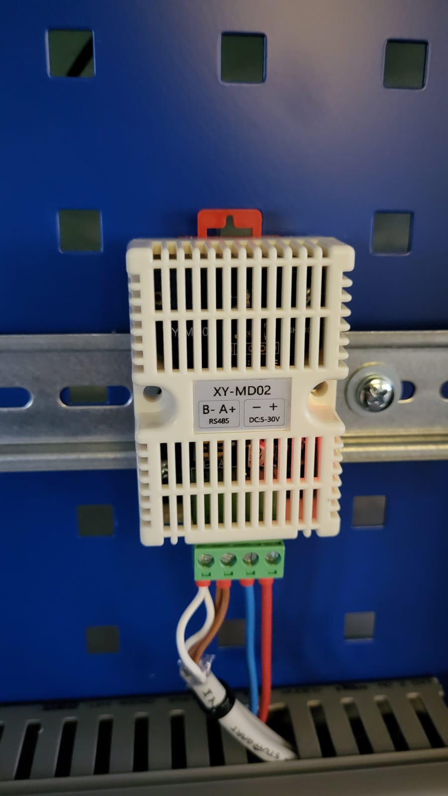
Most Modbus sensors are RTU sensors which only offer serial communication. This standard is called RS485. For our example, we will use a Jiaminye Temperature and Humidity Transmitter RS485 Serial Communication Temperature Sensor. The following image shows what this sensor looks like. Beside the two power lines, there are two communication lines.
But the problem is, Peakboard works best when you can just plug it into a modern network and don’t have to deal with single cables and serial communication from the 80s. That’s why we need a second piece of hardware: a Modbus RTU to Modbus TCP Gateway Serial to Ethernet Converter that translates the serial communication into something that can be addressed with a modern LAN cable.
The actual protocol stays the same; it’s just a physical converter. We usually use the term Modbus RTU for the old style and Modbus TCP for the new style. Peakboard only supports Modbus TCP, and this RTU/TCP converter helps make any Modbus sensor available and addressable from Peakboard.
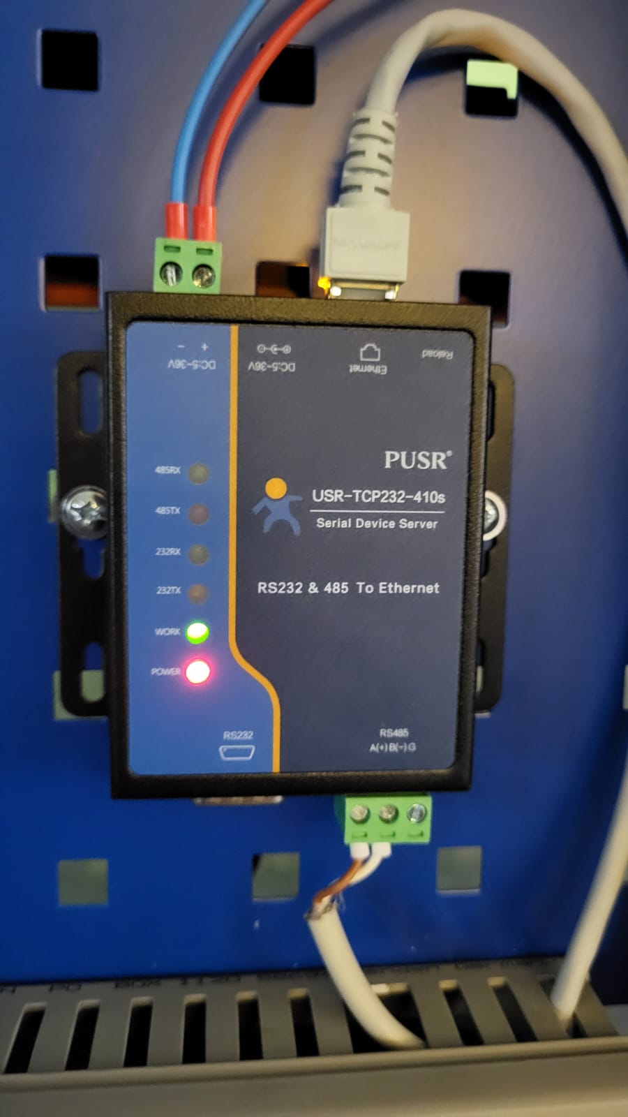
We mount the sensor to the converter, and the converter is available in the same LAN as the Peakboard Box (and Peakboard Designer of course).
Configure the data source
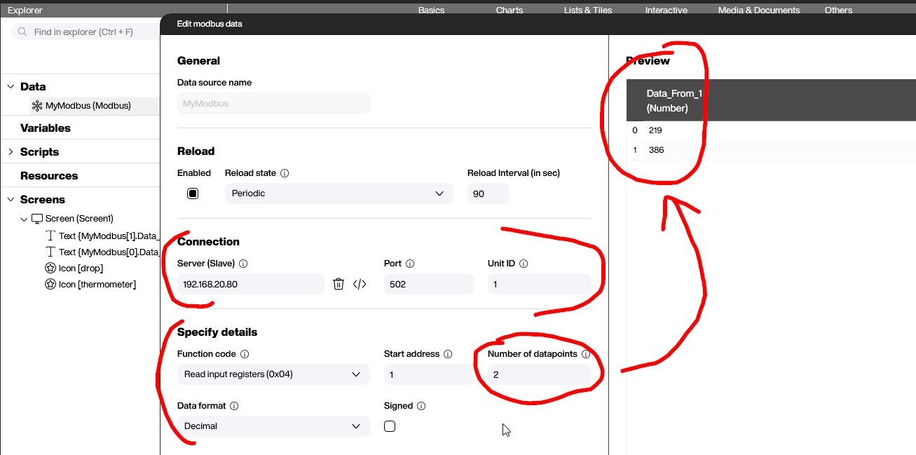
The configuration of the data source is not too complicated, compared to the hardware setup we just did. We need to provide two things:
- The IP address of the RTU/TCP converter.
- The bus address of our sensor within the Modbus bus system (Unit ID). In our case, this is just
1.
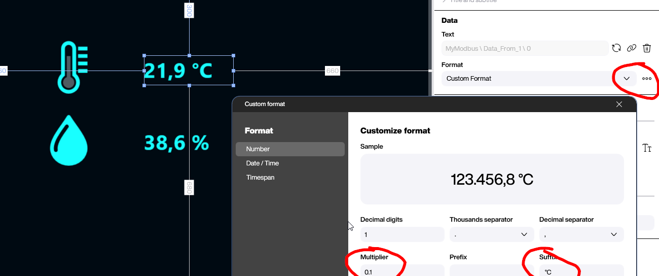
We also specify that we want to read multiple input registers and two data points. Ideally, the preview works right away (see right side) and shows the temperature and humidity data. The temperature is expressed in tenths of degrees, and the humidity is expressed in tenths of percentages.
The following screenshot shows how to format the numbers correctly. There’s no need for any scripting. We just use the standard formatting options to adjust the multiplier, the measure unit, and the number of decimal places. That’s it.
Result and conclusion
As you saw in the article, mastering Modbus with both TCP and RTU is not too difficult, as long as you learn the hardware side and have at least basic knowledge about how Modbus works. And even more importantly, you need to know how the sensor actually works in the context of the serial communication.
Unfortunately, there’s no way around reading each sensor’s documentation. There’s no standard for how the values can be addressed and interpreted. Each vendor has their own implementation.
