ICP DAS is a Taiwan-based company that sells industrial components for automation. In today’s article, we’ll take a closer look at ET-2254, a 16-channel I/O module that provides digital input and output pins, and comes with a cool MQTT interface that makes it easy to create a stable connection to a Peakboard app.
Most customers use the ET-2254 to connect Peakboard to simple sensors, like physical buttons or light barriers. On the output side, we often see customers using it to operate traffic lights and do other binary stuff.
Here’s what the ET-2254 looks like:

And here’s what the setup looks like for the example we’re building in this article. A button is mounted to one of the pins that is later used as an input channel.

The configuration
The ET-2254 comes with a web interface that lets us configure the device’s behavior and connections. In our case, we’re interested in doing three things:
- Configure MQTT.
- Get the input signal for a physical button.
- Send an output signal to switch on a traffic light.
First, we go to the I/O Settings tab. There, we define which pins are for input and which are for output. For our example, we’ll use half-and-half. So, we define the pins D0 to D7 as output, and the rest as input.

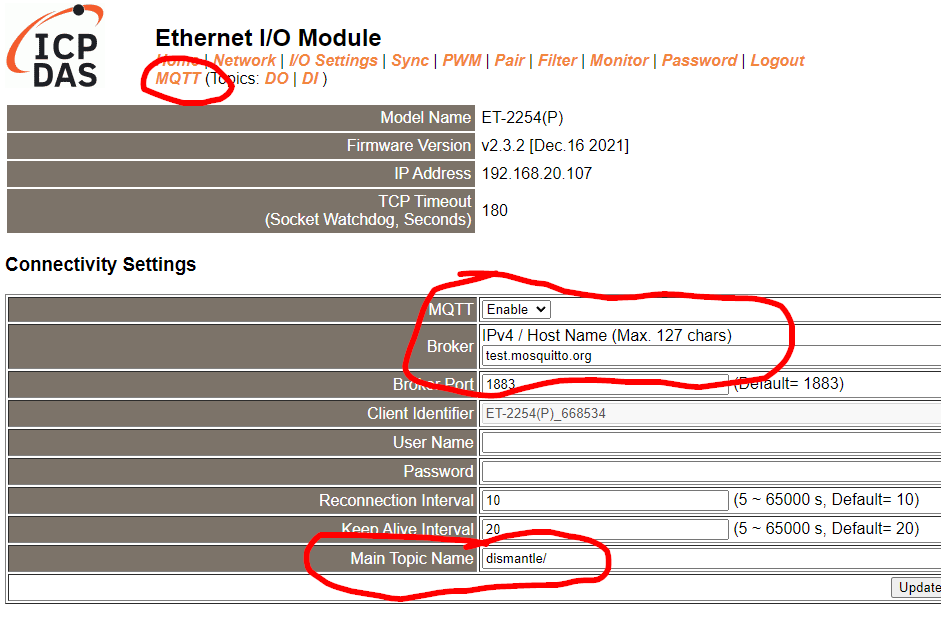
Next, we go to the MQTT tab and connect the device to an MQTT broker. We set the broker to test.mosquitto.org and set the main topic name to dismantle/. All MQTT message exchanges happen under this main topic.
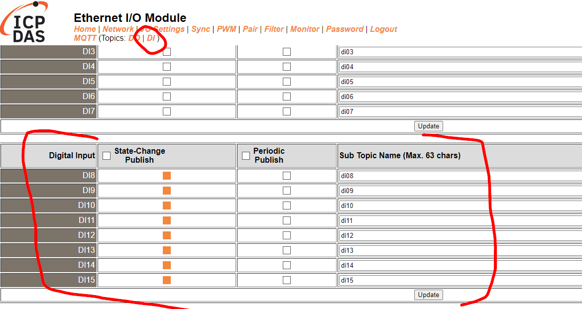
Next, we go to the DI tab and go to the input pins. To make sure that each state change generates an MQTT message, we turn on State-Change-Publish for each input pin.
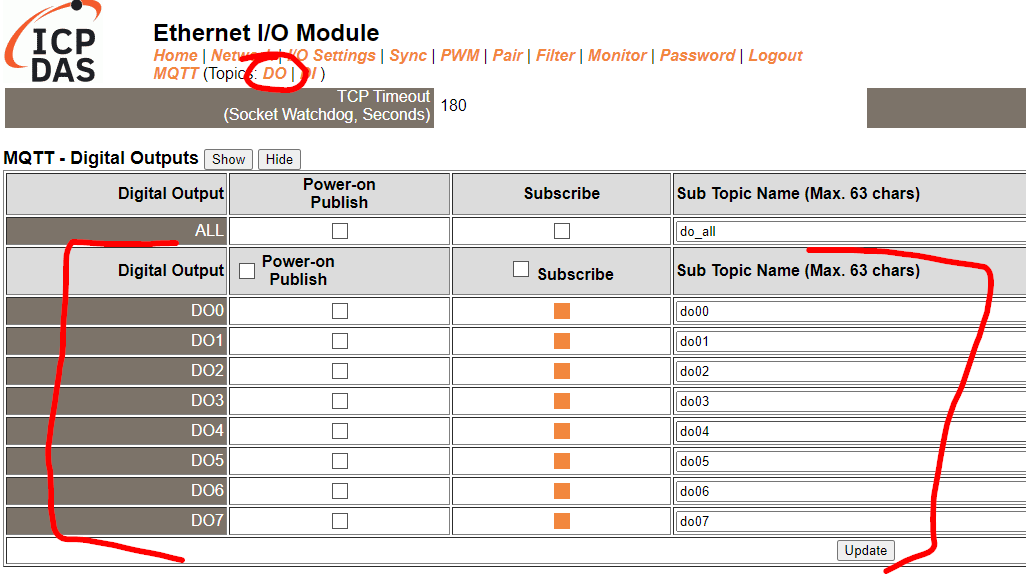
Next, we go to the DO tab and go to the output pins. We want the device to listen to certain topics and then change the state of the output, according to the message that is received. So, we turn on Subscribe for each output pin.
Build the Peakboard application for the input
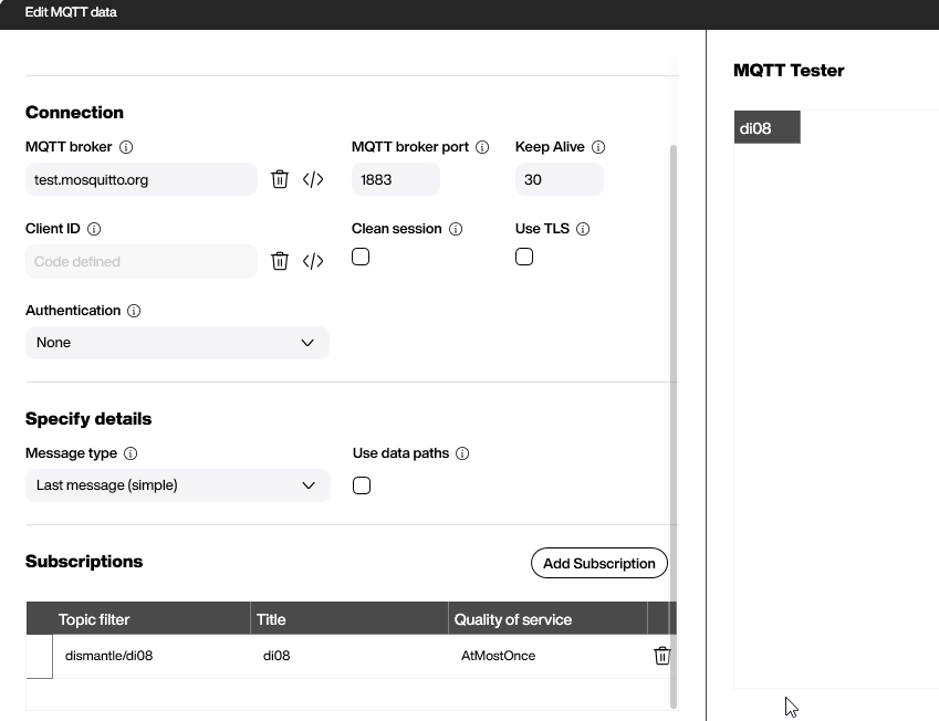
The MQTT configuration is quite simple. We subscribe to the topic for the digital input DI08.
In the Refreshed script, we check the incoming message.
- If it’s
1, that means the state of the input has changed from “no signal” to “signal.” - If it’s
0, that means the state of the input has changed from “signal” to “no signal.”
So every time a 1 is submitted, we increase our counter variable, CounterDI08, by 1.

Next, we put a gray symbol icon on the canvas. With some conditional formatting, we can make the icon green if the MQTT message is 1, which means that the button is pressed or the input signal is set to “on”. Otherwise, the symbol goes back to the default state of gray.
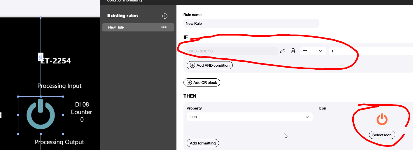
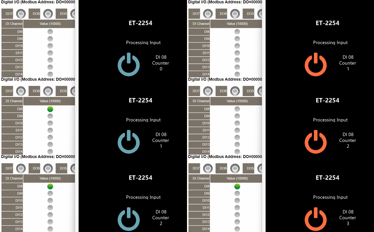
Here’s the result when the physical button is pressed, generating the MQTT message. Note that in the video, our Peakboard application (on the right) reacts much faster than the web interface (on the left), which lags behind by a second.
Build the Peakboard application for the output
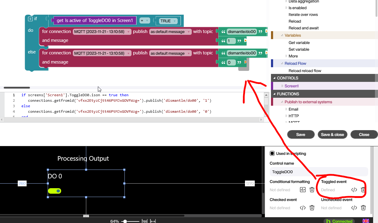
The output signal on the channel DO08 can be set by sending a 1 or 0 message to the MQTT topic we configured earlier. We use a toggle control to switch the channel on and off.
The following screenshot shows how to send an MQTT message through the MQTT Building Block in the Toggled event of the control. For all the LUA lovers, the LUA code can also be seen at the bottom.
And here’s a video of the result. On the right is our toggle button. On the left, we can see the state of the output, as visualized in the web interface of the device. There is still a lag between sending the message and the actual reaction in the web interface. This is purely a web interface problem. The actual output channel is switched according to the MQTT message without any significant latency.

