In The hitchhiker’s guide to I/O devices we lined up five I/O blocks and compared them on connectivity and price. All five shared something we never bothered to mention, because there was nothing to mention: the I/O count was printed on the box. A WISE-4012 has four inputs and two outputs. An ADAM-6051 has twelve and two. We buy the shape we need, and the datasheet tells us which register holds what.
The Synergy Logic SLM family doesn’t work like that. Today’s article is about what changes when the address map depends on what we plugged in.
What it is, and what it isn’t
It looks like a PLC, so let’s clear that up first: it isn’t one. There’s no CPU running logic, no ladder to download, no runtime to deploy. The SLM-MX is a bus coupler — a Modbus TCP server with a rail of modules behind it. Peakboard talks to it directly, with no controller in the way. There’s nothing to program except the dashboard.
The rack we were sent:
| Part | What it does | Price |
|---|---|---|
| SLM-MX | Bus coupler / Modbus TCP server. Maps up to 8 slots into one register table. | $99 |
| SLM-SIM-8 | 8 discrete inputs — physical toggle switches on the module itself. | $52 |
| SLM-RLY-16 | 16 relay outputs. | $126 |
| SLM-AI4-AO2-mA | 4x 0-20 mA analog in, 2x 4-20 mA analog out. | $191 |
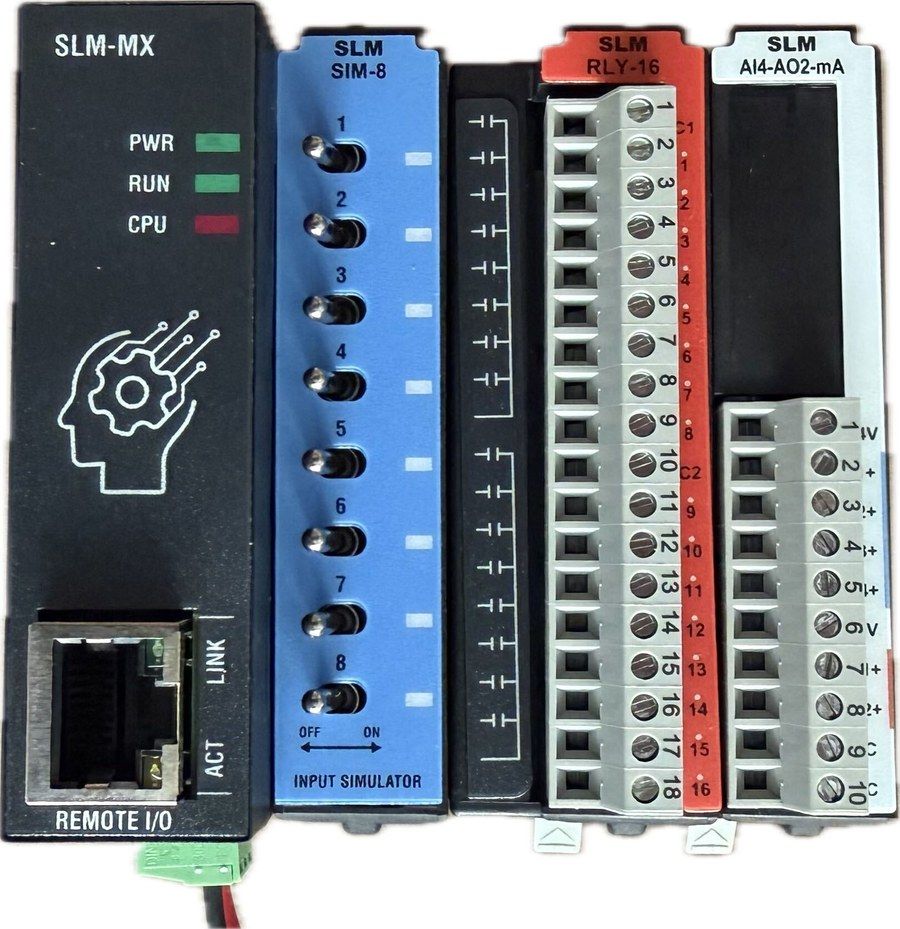
Left to right: the coupler with its Ethernet port and PWR / RUN / CPU LEDs, then the three modules in slot order.
The SIM-8 deserves a moment. It’s a simulator module: eight real switches we flip with a thumb. That means an entire input path — switch to register to dashboard — can be proven with nothing wired to anything. Add relays we can hear clicking and the whole demo runs on a desk with a single power supply. More vendors should sell one of these.
Two things to know before plugging in. Port 502, and DHCP by default — the 169.254.10.10 in the docs is only the APIPA fallback for when no DHCP server answers. And eight TCP connections in total: a Designer session, a running Peakboard Box and a polling tool will spend most of them between them. If connections start getting refused during bring-up, close something.
First contact: when a Modbus error is good news
We pointed a browser at it and got nothing. That’s correct — there is no web interface. A port scan turns up 502 and nothing else. Every other device in the guide has a configuration web page; this one has a Windows desktop app instead.
So we went at it with Modbus reads, and got something that looked like a broken device:
| Probe | Result |
|---|---|
| FC1 read coils @0 x16 | OK - all zero |
| FC1 @1000 | exception 0x02 |
| FC2 read discrete inputs @0 | exception 0x07 |
| FC3 read holding registers @0 | exception 0x07 |
| FC4 read input registers @0 | exception 0x07 |
One function code works, three refuse everything. The tempting conclusion is “our addresses are wrong” — and the difference between those two exception codes is exactly what tells us it isn’t:
0x02Illegal Data Address means “that address doesn’t exist.” That’s an addressing problem, so we keep hunting offsets.0x07Negative Acknowledge means “I won’t serve this.” Not the address — the whole function code, at every address we try.
Three entire function codes refused isn’t an off-by-one. It’s a device telling us it has no register map yet, which is exactly right. The SLM-MX ships unconfigured, and the discrete input and register tables do not exist until modules have been declared. Only the coil table is statically allocated, which is why FC1 alone answered.
That’s worth keeping hold of in general: on a Modbus device that seems dead, 0x02 and 0x07 send us to opposite ends of the building.
The LEDs agree, if we know the table. Run off with CPU blinking red is awaiting configuration. One trap: firmware updating is the same pattern, differing only in blink rate. If it’s blinking fast, don’t power-cycle it.
Configuration
The tool is the SLM-MX Configurator, a Windows desktop app shipped as an .msix. Let it through when the installer asks for network access.
Type the IP address in rather than scanning for the device. Discovery uses UDP multicast, which needs multicast enabled on the switch, IGMP snooping off, port security not blocking a new MAC, and firewalls passing UDP. Synergy’s own docs say manual entry is the most reliable method, and if we already know the address then that entire failure surface is optional.
There’s no hot-swap. We power down before adding or removing a module, and re-send the configuration afterwards:
- Power down, fit the modules, and write down the slot order.
- Power up. The Configurator auto-detects and shows a card per module — there’s no manual declaration step.
- Hit Configure and wait for each card to go green.
- Export the Modbus Registers Map. Keep that file.
The Configurator draws one card per detected module, in rail order, with a Configure button to commit the lot. Here’s our rack: the coupler, then SIM-8 in slot 1, RLY-16 in slot 2 and AI4-AO2-mA in slot 3. Note the eight little toggle switches drawn on the SIM-8 — those are real, and they’re about to do all our testing for us.
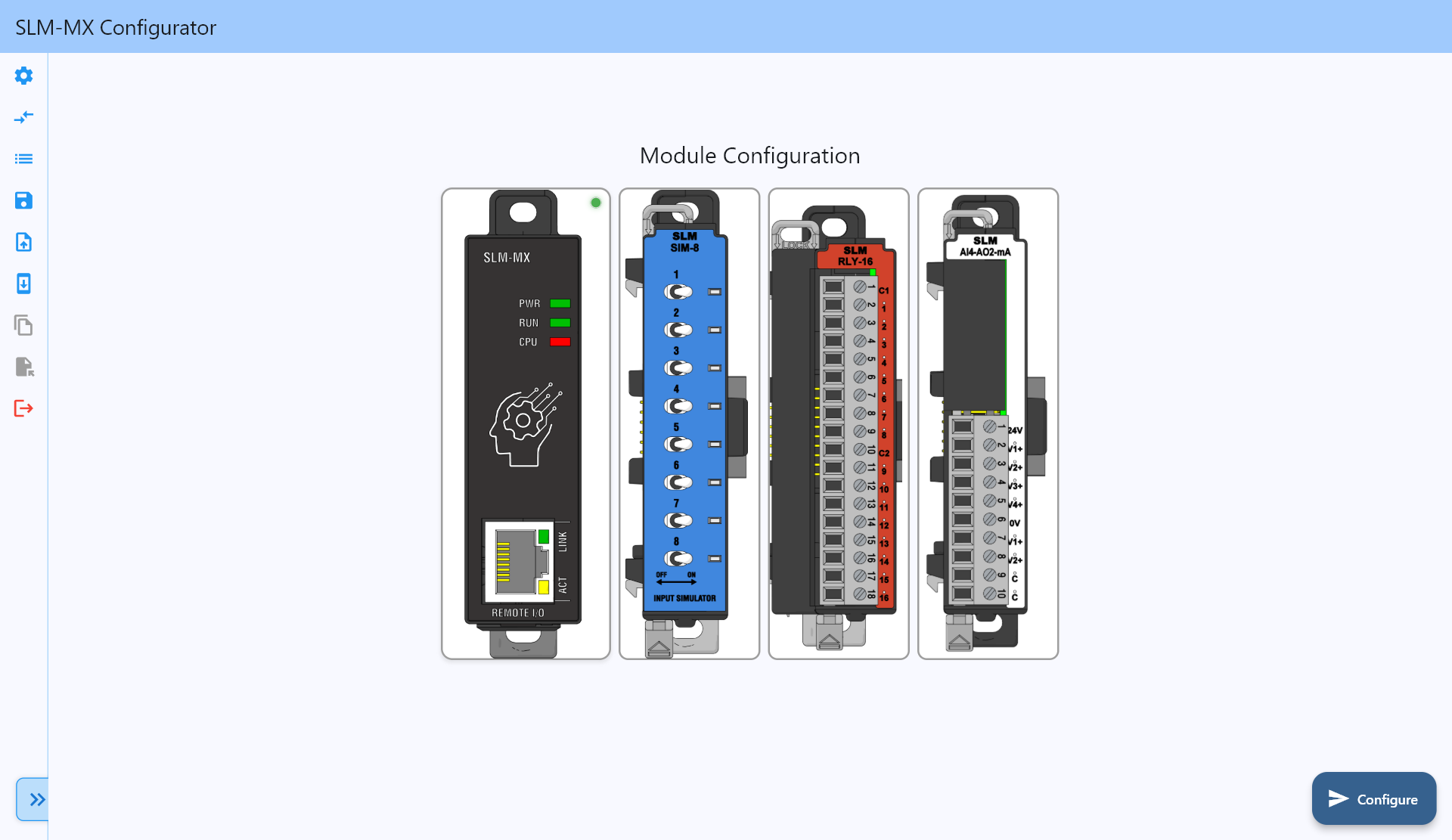
Worth holding on to that picture, because the obvious conclusion it invites is the wrong one — more on that shortly.
Re-running the probes, the picture changes: FC2, FC3 and FC4 all start answering. But the single most informative line is this one:
| Probe | Before | After |
|---|---|---|
| FC3 read holding register @0 | 0x07 |
0x02 |
Holding registers went from “won’t serve” to “no such address.” To a caller both are still failures, but the meaning has flipped. The map now exists, and simply has no holding register at 0 yet. 0x07 was never an addressing problem.
The address map, and the mistake we made in it
The first trap is universal to Modbus. Synergy’s docs print addresses in Modicon display notation: 000001, 100001, 300001, 400001. Peakboard’s Start address is the zero-based protocol offset. The first relay is start address 0 with function code 1. Not 1, and certainly not 000001. We covered the same trap from the serial side in Modbus Madness.
The second trap is specific to modular I/O. We probed the ranges the coupler would serve:
| Space | FC | Valid range | Per slot |
|---|---|---|---|
| Coils | 1 | 0-127 |
16 |
| Discrete inputs | 2 | 0-127 |
16 |
| Input registers | 4 | 0-63 |
8 |
| Module status bits | 2 | 1000-1127 |
16 |
8 slots x 16 = 128. 8 x 8 = 64. Clean, obvious, and it invites exactly one conclusion: each slot owns a fixed block, so a module in slot N starts at (N-1) x 16.
That conclusion is wrong, and we worked to it for two days before catching it.
Look back at that Configurator screenshot: SIM-8 in slot 1, RLY-16 in slot 2, AI4-AO2 in slot 3. Under the slot formula the relays should sit at coils 16-31. They’re at coils 0-15. The real rule:
Addresses pack densely from 0 across the channels that actually exist, in slot order. An empty or non-matching slot consumes nothing.
Those 0-127 and 0-63 ranges are a reserve for eight slots. They are not a map. Only the first N addresses are backed by real hardware.
Why the wrong formula survived is more useful than the formula itself: the SIM-8 was the only input module, and it sat in slot 1. Both models predict discrete inputs 0-7 for that. Every check we ran happened to be a case where the two models agree, so every check “confirmed” it. The first probe that could tell them apart was writing to a coil and listening.
Walking coils 0-15 on, then 16-23, then releasing 0-15 gave us clicks, silence, clicks. Under the slot formula the identical test gives the exact inverse — silence, clicks, silence. That’s the difference between a test that confirms a belief and one that can break it.
And the Configurator’s export had been saying so all along:
SLM-SIM-8        slotIndex=1   discrete in    posStart=0    channels=8
SLM-RLY-16       slotIndex=2   coils          posStart=0    channels=16
SLM-AI4-AO2-mA   slotIndex=3   input regs     posStart=0    channels=4
SLM-AI4-AO2-mA   slotIndex=3   holding regs   posStart=0    channels=2
posStart=0 on every one, at slot indices 1, 2 and 3. Each space is numbered from zero independently, and the slot index never enters into it. Export the map, read the posStart values, and believe them over any formula we’ve talked ourselves into — including this one.
So our rack resolves to:
| Module | Space | Function code | Addresses |
|---|---|---|---|
| SLM-SIM-8, 8 in | Discrete inputs | 2 | 0-7 |
| SLM-RLY-16, 16 out | Coils | 1 read / 5 write | 0-15 |
| SLM-AI4-AO2, 4 in | Input registers | 4 | 0-3 |
| SLM-AI4-AO2, 2 out | Holding registers | 3 read / 6 write | 0-1 |
The corollary is the part to remember: because addresses pack, any change to the rack renumbers everything downstream of it. Pull the SIM-8 and every analog input shifts. There’s no stable slot-derived address to fall back on. Re-export and re-verify after touching the rail.
The silent failure
This one deserves its own heading.
We wrote to coils 16-39 — addresses inside the reserve, backed by nothing at all. The device returned a normal Modbus write echo. Not an exception. The value simply vanished. Reading the same region returns clean, plausible zeros.
A Peakboard application pointed at the wrong address looks completely healthy. Writes are acknowledged, reads return tidy zeros, nothing is logged, and no layer of the stack raises anything we could catch.
A dashboard sourced from an empty slot renders a column of zeros forever. If someone pulls a module next year, it carries on showing plausible data.
The only honest proof that an output address is real is physical actuation: write the coil, hear the relay close. For inputs, flip a switch and watch the value move. Do it once per address block during bring-up and write down what was proven.
While we’re there, it’s worth proving the bit order too, with an asymmetric pattern. We set toggles CH1 + CH2 + CH5 and read back 0b00010011, which confirms CH1 is the least significant bit. A symmetric pattern like CH1 + CH8 returns the same byte on an MSB-first device, and we’d have shipped an application with every channel silently reversed.
Connecting it to Peakboard
Now the easy half. Peakboard speaks Modbus TCP natively, so we need one connection and one data source per block.
The connection is three fields: the IP address, port 502, and a Unit ID. The SLM-MX ignores Unit ID entirely — 0, 1, 2 and 255 all behave identically. Peakboard wants a value, so we put 1 and read nothing into it.
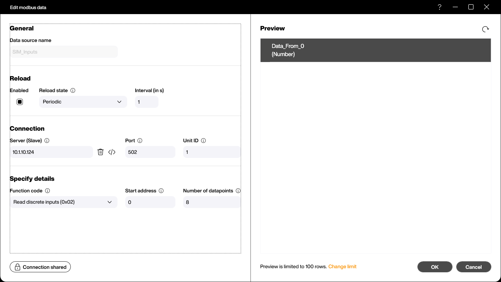
The relay block is the same dialog with function code Read coils (0x01) and 16 datapoints:
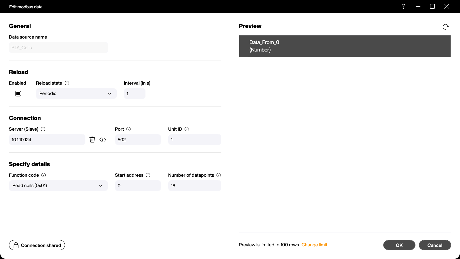
One detail in that screenshot surprises people: the preview shows one column, always called Data_From_0, with one row per datapoint — not one column per register. Eight discrete inputs come back as eight rows, indexed zero-based like any other list:
local n = data.SIM_Inputs.count
for i = 0, 7 do
   if i < n then
      if data.SIM_Inputs[i].Data_From_0 > 0 then
         screens['SLM-MX']['InLed' .. i].background = brushes.fromhex('#FF007A43')
      else
         screens['SLM-MX']['InLed' .. i].background = brushes.fromhex('#FFC2D0DA')
      end
   end
end
The reload interval is worth setting deliberately, too. The default is 90 seconds, which is fine for a stock level and useless for live I/O. We run these at 1 second.
Writing back: relays need Lua
Reads are declarative. Writes are not. There’s no “write” data source — every output goes through script, using two functions on the connection:
connections.getfromid('<connection-id>').writesinglecoil(0, true)      -- relay 1 on
connections.getfromid('<connection-id>').writesingleregister(0, 16383) -- analog out, raw
Our relay buttons toggle, so we read the coil, invert it, and write it back:
local i = tonumber(idx)
local cur = 0
if data.RLY_Coils.count > i then
   cur = data.RLY_Coils[i].Data_From_0
end
local want = true
if cur > 0 then
   want = false
end
connections.getfromid('<connection-id>').writesinglecoil(i, want)

-- repaint immediately, then let the next poll tell us the truth
local s = screens['SLM-MX']
if want then
   s['RlyLed' .. i].background = brushes.fromhex('#FF007A43')
else
   s['RlyLed' .. i].background = brushes.fromhex('#FFC2D0DA')
end
data.RLY_Coils.reload()
Those last lines matter. reload() is non-blocking — it requests a refresh and returns immediately. Without the optimistic repaint, the LED lags the relay by up to a full poll interval and the application feels broken while working perfectly. So we paint what we asked for, then let the next poll overwrite it with the truth.
That also buys back a little of what the silent-write problem took away. If the write didn’t land, the LED lights and then snaps back within a second. It isn’t an error we can catch in script, but it is something a human can see.
One UI note: the relay controls should be buttons, not tapped rectangles. Only a button renders a pressed state, and on a touch panel driving physical relays the absence of any acknowledgement is unpleasant to use.
About the analog module
Honest disclosure: we haven’t verified this part on hardware. The AI4-AO2 needs field 24 V on its analog section that we haven’t wired, so it currently reports 24V Missing and reads zero. What follows is from documentation and probing, so check it rather than trusting it.
The thing to know is that the scaling is 13-bit, not 16-bit. Peakboard reads a raw uint16, but the module only uses 0-8191:
- Inputs (0-20 mA):
mA = raw * 20 / 8191 - Outputs (4-20 mA):
raw = (mA - 4) * 8191 / 16
Outputs are offset as well as scaled. 4 mA is raw 0 and 20 mA is raw 8191, so writing 0 doesn’t mean “off” — it means 4 mA, a perfectly valid live signal. If we’re driving a valve, that distinction matters rather a lot.
Result
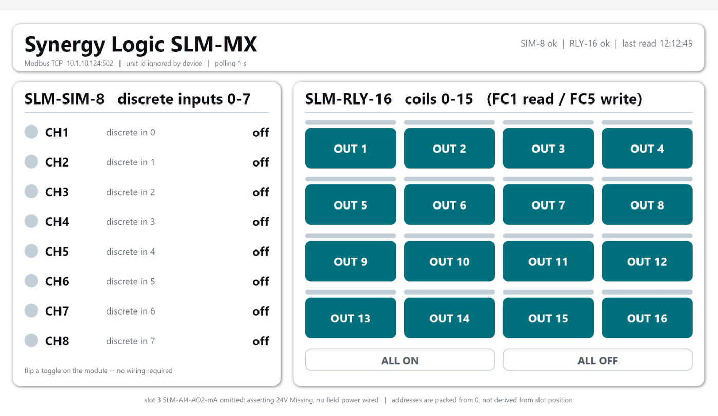
A single 1920x1080 screen: eight indicators mirroring the SIM-8 toggles on the left, a 4x4 grid of relay buttons on the right, plus ALL ON and ALL OFF.
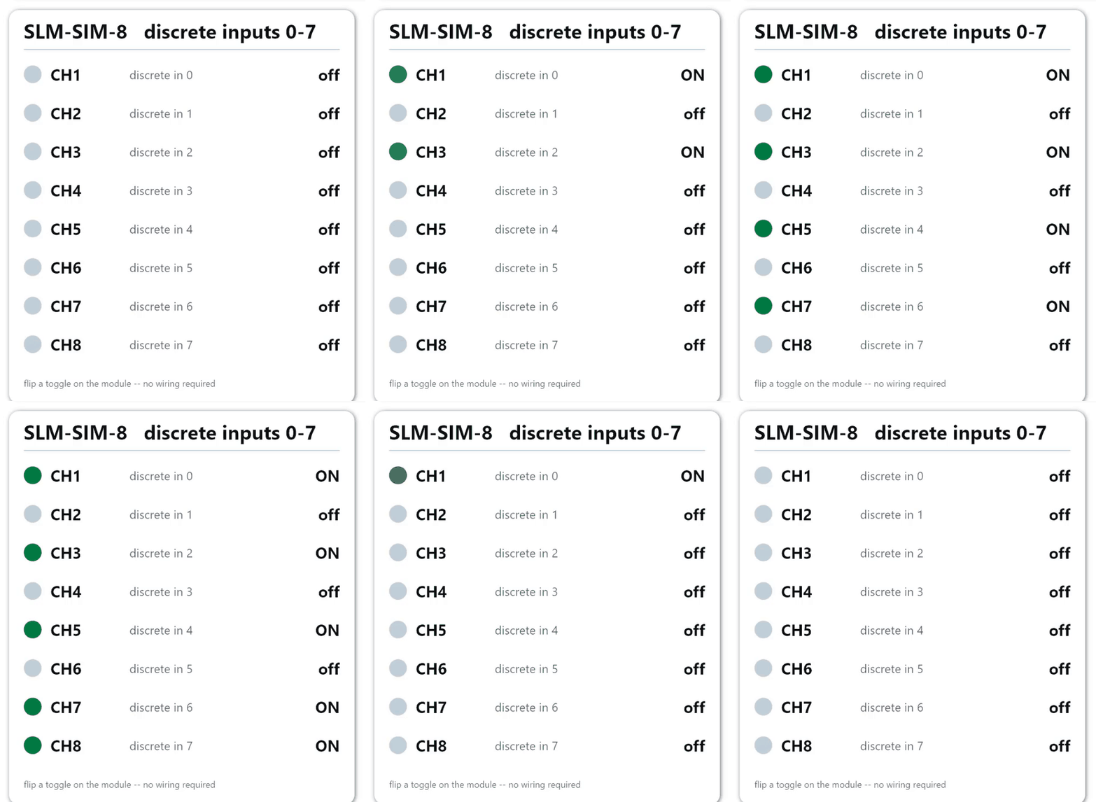
Flipping the switches on the module updates the dashboard within a second:
And tapping the buttons writes coils straight to the relay module, which we can hear as well as see:
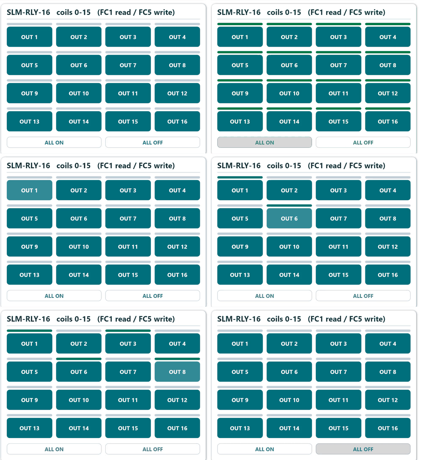
Both directions, and with nothing wired to anything.
The whole application is available for download at the top of this article. It hard-codes the IP address of our bench device, so the first thing to change is the server address on the Modbus connection — and given everything above about writes disappearing silently, the second thing is to confirm the addresses match whatever is actually on the rail.
So where does it sit in the guide?
Against the fixed-function blocks, the SLM family trades convenience for shape.
What we give up. No web UI, so configuration means a Windows app on somebody’s machine. No MQTT and no OPC UA — it’s Modbus TCP or nothing. No hot-swap. And an address map that depends on what’s plugged in rather than what’s printed in the datasheet.
What we get. Up to eight modules behind one IP address and one Peakboard connection. If we need 48 relays, or 16 relays and 12 analog inputs, or we expect the I/O count to grow, we pick another module instead of picking a different product. The fixed blocks can’t do that at all.
On price it’s competitive rather than cheap: $99 for the coupler, and around $191 for a usable 16-input node once a module is on the rail. That’s roughly where the fixed blocks in the guide sit, except here the number goes up as the rack grows — and the range runs to thermocouples, AC inputs, isolated relays and 0-10 V without anything changing on the Peakboard side.
Once the map is right there’s nothing clever left to do. Modbus TCP is the plainest transport in the guide and Peakboard supports it natively. Our advice in one line: export the register map, verify every block by physical actuation, and write both down. On hardware that acknowledges writes into the void, the notes we take during bring-up are the only diagnostics we will ever have.